E-commercial.jpg

E-Mobility for the Truck Market

One-Stop-Solutions from Continental

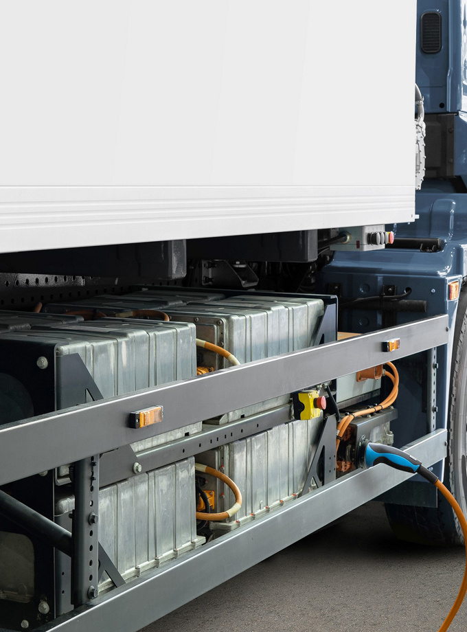
E-Commercial vehicles are quickly becoming a reality, and manufacturers are entering a challenging market.
We at Continental are your specialist for e-vehicle hardware and software.

Overview

Market Demands

Increasing demand for alternative powertrain concepts in the CV market.

Worldwide emission regulations – OEMs need to move fast to bring their solutions to market.

Technological uncertainties with regards to energy carriers, low volumes and high investment costs make profitable investments harder.

Charging infrastructure will need to be developed to guarantee reach and availability also for commercial vehicles.

Sustainability: Prove CO2 neutral production + global CO2 emissions also valid for trucks.

An icon with a gray circular background outlined in orange, featuring a bar graph with a rising trend line and an arrow pointing upwards. "Market Demands" is written in bold black text below the graph.

In this complex field, manufacturers need an experienced partner to help them deliver the right solutions.

Our Portfolio – Our Solution

holistic_icon_grau.png

With our holistic approach, we offer a comprehensive portfolio in e-vehicle hardware and software.

consulting_icon_grau.png

From requirements definition and consulting to pre-development demos, up to the SOP and after series support – we deliver solutions along the complete product lifecycle.

know-how_icon_grau.png

This deep know-how is completed by our substantial product range for all hardware and software solutions for e-vehicles and infrastructure.

Our Sustainability Ambition

Our Key Ambitions

By 2050 at the latest, we and our value chain partners are striving for:

10

100% Carbon neutrality

along our entire value chain

9

100% Emission-free mobility and industry

11

100% Circular economy

11

100% Responsible value chain

02

Good working conditions

05

Safe mobility

02

Green and safe factories

06

Long-term value creation

03

Innovations and digitalization

07

Sustainable management practices

04

Benchmark in quality

08

Corporate citizenship

Continental - Your Partner for E-Mobility

With decades of CV specific customer experience for architecture, electronics, a dedicated electronics development team and a global CV organization, we are well equipped to cover all customer needs around EV electronics.  

  • On the way to zero emission production (carbon neutrality)
  • Dedicated development team with 500+ employees focused on electrification solutions worldwide
  • Development and validation infrastructure: testing, vehicle workshops, test benches
  • Global manufacturing footprint for low, mid, and high volumes with reuse of manufacturing investments
  • Many years of experience in electrification with proven track record
  • Cybersecurity + functional safety expertise  

Our Offer – High Level Overview

We are your partner of choice towards  emission free mobility in the CV market. We offer solutions for E-Mobility along the complete product lifecycle in the areas of:

13

Architecture & Consulting

System Integration, E/E-Architecture, Vehicle development and prototype build

14

Software

Basic Software, Application Software, Autosar

15

Product Development & Products

Power Electronics (up to 1000 V), Low Voltage Electronic Control Units , Powertrain Auxiliaries

e_mobility_architecture_consulting.jpg
E-Mobility for the Truck Market 

Architecture & Consulting

Architecture and Consulting

One Stop Shop Partner

  • Feasibility Studies
  • Requirements
  • Topologies, E/E-Architecture
  • Component Dimensioning
  • Performance Simulation
  • Development Plan

  • Component Development
  • Vehicle Development
  • Software and Control Development

  • Technology Demonstrators
  • Test Vehicles
  • Fleet Vehicles
  • System Integration
  • Commissioning
  • Logistics

  • Performance
  • Robustness and Reliability
  • Safety and Misuse
  • Crash Tests
  • Prove of Legal Compatibility

  • Homologation
  • NEV Market Entry
  • Industrialization
  • Launch Support
  • Production Support
e_mobility_software.jpg
E-Mobility for the Truck Market 

Software

Software

While the customer can focus on SW development, we ensure the industrialization of the product.

Benefit from SW/HW experienced supplier with comprehensive AUTOSAR and security competences.

  • Model-Based-Development-System for efficient application development.
  • Wide portfolio and experience in the area of E-Mobility/driveline, body and chassis applications.

We master base software and complexity of integration (customer-, Continental- or third-party SW parts) while customer can focus on his core competences /
application level.

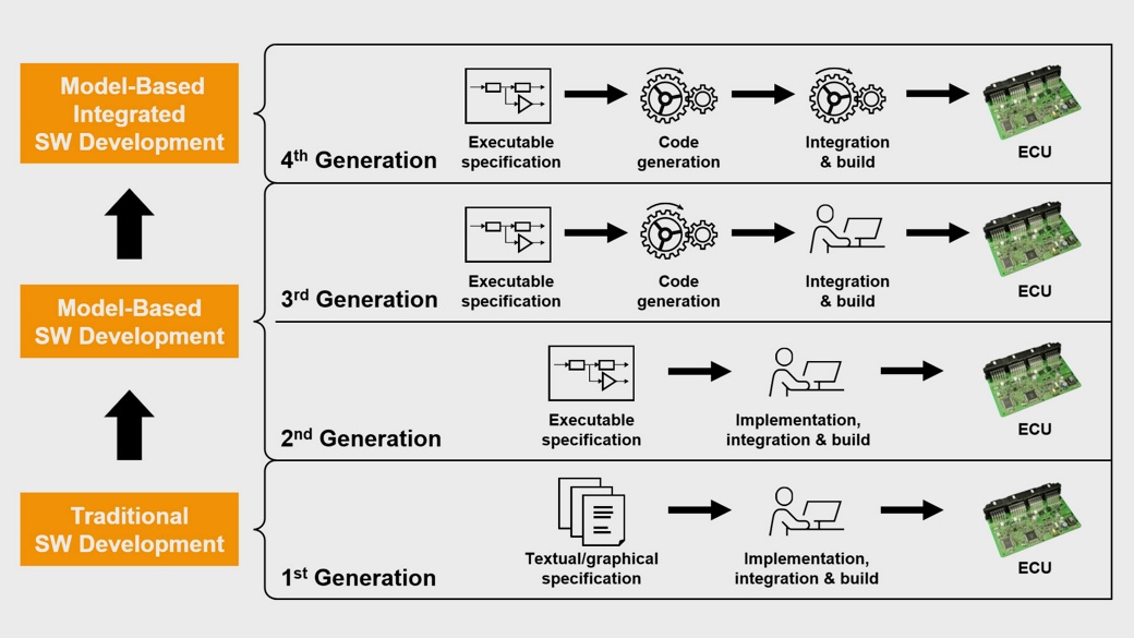
Benefit from 4th Generation of embedded platform

  • Model-Based-Development-System
  • Aligned HW to accelerate time-to-market
  • Agile framework and strong automotive partners

Customer software care and competencies needs
An orange bidirectional arrow pointing up and down, with the text "Supplier responsibilities" written vertically along the length of the arrow.

Platform and AUTOSAR Competence

4th generation of embedded platform covers AUTOSAR complexity by advanced toolset to accelerate development:

Configuration instead of Programming

Applicable for all kind of embedded devices

  • Easy-To-Use tool chain allows application development and integration by customer
  • Expert tool chain for projects with needs for highest flexibility and adoptability

Manages embedded challenges as

  • Different processor families and multicore
  • Scalable connectivity
  • Safety (up to ASIL-C)
  • Security and many more  

Generation CoVeR

Logo from Elektrobit
Autosar_Logo
  • AUTOSAR
  • Security
  • Hybrid, Connectivity
  • MultiCore

Generation RT3/RT3-PL

  • Multi Tasking
  • ASIL B
  • PremiumLine ARM Core
  • LogiCAD 3

Generation RT2

Logo from Matlab & Simulink
  • Matlab/Simulink
  • Generic CAN
  • FR80 Core

Generation RT1

  • Model based development
  • LogiCAD 32BIT µC
  • VGC Core
  • More than 18 years of System Solutions Experience
  • Focus on development cost optimization for OEM
  • Focus on improve Time to Market

4th Generation of Software Development

Unique approach with focus not only on target software, allows

  • Benefits of high reuse of existing HW and SW solutions
  • The seamless integration of development tools for high automation and focus on the essential tasks  

Needs to support the wide spectrum of commercial vehicle electronics

  • Applied for Body controller, vehicle control units, Instrument cluster
  • Used in more than 100 projects

Ready also for E-Mobility applications

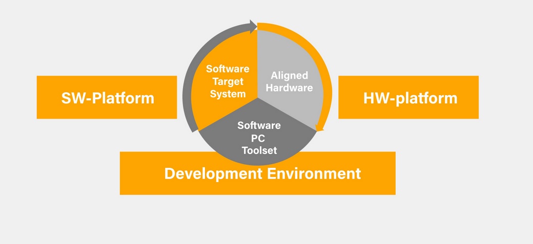
Graphic about Software Development
 A diagram illustrating the integration of software and hardware platforms within a development environment. The central circle, divided into three sections—Software Target System, Aligned Hardware, and Software PC Toolset—is surrounded by labels: SW-Platform, HW-Platform, and Development Environment.

Agile Planning Approach

Agile development improves

  • Focus on features with highest value added
  • Flexible re-prioritization of development targets
  • Avoiding wasted planning and process efforts

Rolled-out agile process based on SAFe
(Scaled Agile Framework)

SAFe logo
ZONAR logo
Elektrobit logo
DIGILENS Logo
ARGUS Logo
Bild3.jpg
E-Mobility for the Truck Market 

Product Development & Products

Product Development & Products

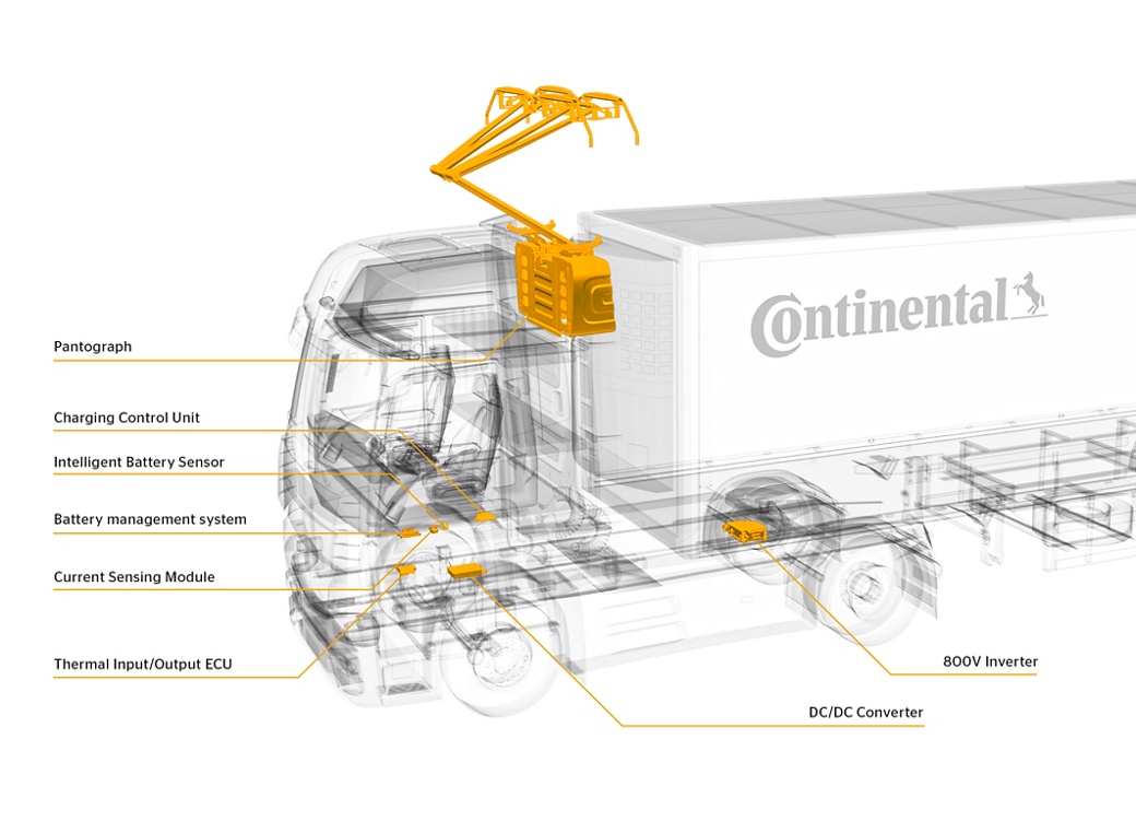
Product Overview

  • DC/DC Converter
  • Battery Management System (BMS)
  • Pantograph (eHighway)
  • Electric Vehicle Charging Controller
A transparent rendition of a truck with marked and labeled components including a pantograph, charging control unit, intelligent battery sensor, battery management system, current sensing module, thermal input/output ECU, DC/DC converter, and an 800V inverter.

  • Receives and processes data from the connected sensors and actuators and provides output signals to other ECUs on the Auxiliary CAN.  
  • Provides control interfaces to the connected sensors/ actuators via signal interfaces on the Auxiliary CAN.
  • Acts as an intelligent gateway ECU and contains SW to fulfill the standard
    diagnostic and network requirements.
  • Needs to process signals and execute OEM in-house functions.

  • All electric long-haul truck (Tractor/ rigid)
  • Can Interface: CAN-FD
  • Operating Temp.: -40…+105°C
  • IP Class: IP6K9K
  • ASIL: B
CBCU5

Illustration of a semi-truck with a transparent view, highlighting an automotive electronic control unit (ECU). Arrows point from the ECU to icons of a battery and a charging station, indicating its connectivity to these components.

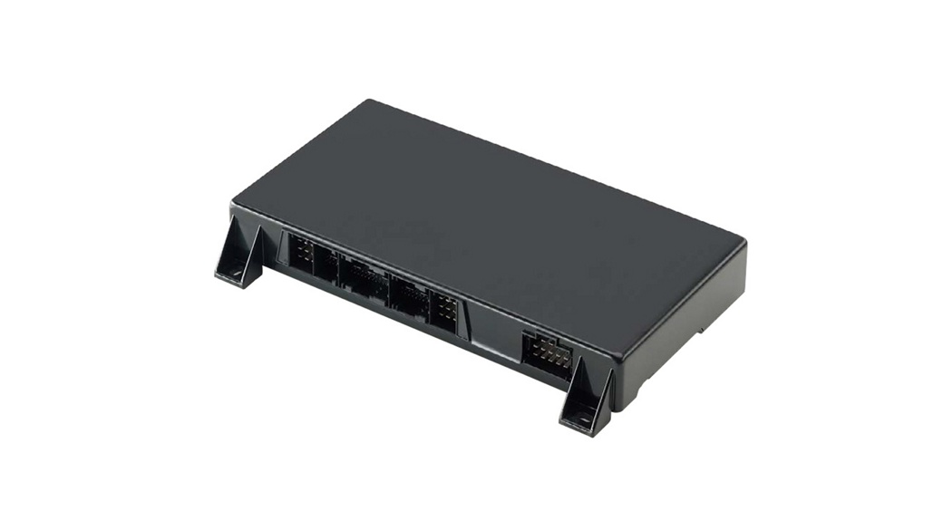
  • The Vehicle Charging Controller is a generic 12V/24V Unit for use in electrified commercial vehicles.
  • It realizes electrical charging according to DIN and ISO requirements for power line communication (PLC and MCS) with the infrastructure needed at EU, NA and Asian Market.
  • Full electric target vehicles are light, medium and heavy trucks, solo and articulated buses.
  • The HW will be designed and produced by Continental, programmed with customer developed software and charging application.

  • ASIL-B to ASIL-D hardware design possible
  • Variants, realized on same PCB with diff. component assembly
  • OEM specified connector
  • Separate connectors to adapt the Variants to periphery
  • Optional foreseen Ethernet single Phy
  • IFX Controller TC3xx, BGA516
  • Several IO hardware interfaces for infrastructure needed at EU, NA and Asian Market
  • 2...5CAN interfaces, LED signal drivers for inlet covers OEM needs
  • Housing IP-Class IP50 to IP6k9k covers OEM needs
  • Mounting in cabin, on Frame or top on roof for busses
  • Different variants are planned to cover known truck and bus applications at different markets.
  • The Controller will be built and delivered as standard unit and in an extended version with Ethernet functionality
  • The standard unit be used as an interface controller with full support of cable-based inlets.
  • The extended version, be an interface between vehicle side and the charging station, with full support of cable-based inlets, roof mounted pantograph and inverted pantograph.
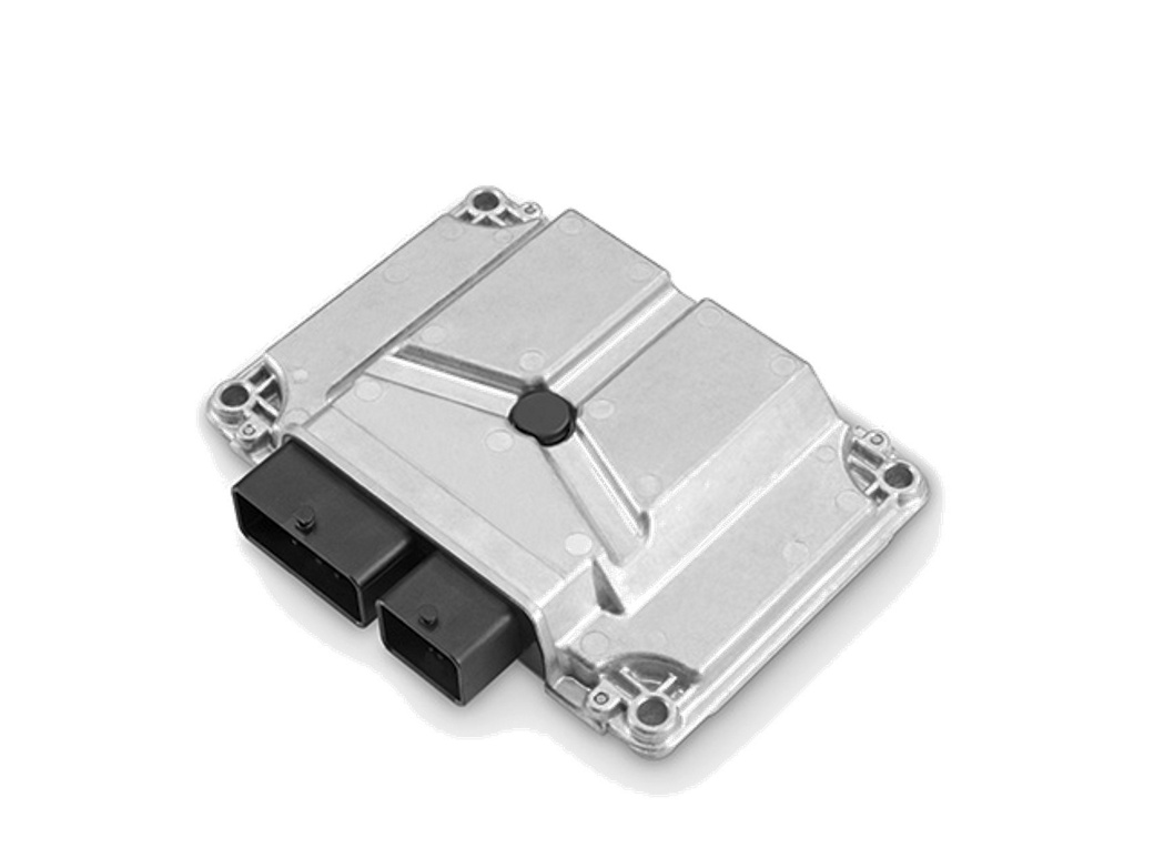
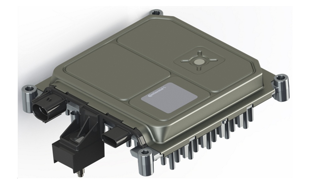
An electronic control unit (ECU) with a metallic casing and multiple connectors on one side. The unit is rectangular and features a slightly raised, angular design on the top surface, with mounting holes at each corner. The background is plain white.

The Continental Power Line Communication controller provides a modern and smart PLC to CAN gateway to the car and its passengers. It is the communication interface between the Electric Vehicle Supply Equipment (EVSE) and the Electric Vehicle Central Control Unit (vehicle charging functions).  

  • AC/DC fast charging communication​
  • Plug and Charge (PnC)​
  • Bidirectional Power Transfer (BPT)
  • Self-Test and Diagnostics via UDS
  • Smart Charging
  • Safety ASIL B (D)
  • FOTA (over-the-air update) capable
  • IP42 (optionally IP6k9k)
  • Dimensions: 70mm x 120mm x 27mm
  • Weight: 110g

  • Provide operating system and hardware abstraction software in AUTOSAR environment
  • Provide Continental application software, Adapt functional to OEM specificities
  • Support System Integration and System Test
  • Support prototyping, qualification
  • Industrial encapsulation and production launch
  • Deliver serial parts – Reduced time to market

  • Compliant with PLC norms ISO 15118 and DIN 70121
  • CHAdeMO supported optionally
  • Charging Communication over CP signal according to IEC 61851
  • Modular Design allows for easy individualization and integration of 3rd party applicative software
  • Cyber security concept protecting against external threats and including secure
    reprogramming using a dedicated HSM core
  • Up to ASIL D Charge System Performance
  • Proven in series application - Reduced time to market
A close-up view of two electronic control modules, one rendered as a physical device and the other as a digital CAD model. The physical module features several ports, including a noticeable blue RJ45-like connector.

  • Acoustic Vehicle Alerting System (AVAS) is an obligatory sound generator for electric and hybrid vehicles that generates a synthetic speed related driving sound to increase the pedestrian’s and other road user's safety by alerting them about an otherwise silently approaching vehicle.
  • The system consists of an ECU and 1 (basic) or up to 5 (premium) actuators which can be mounted to any exterior body structure.

  • Extra wide radiation of sound due to excitation of the surface
  • Flexible integration due to small dimensions and weight
  • Higher resistance against media than a conventional speaker (water, dust and shock)    

Ac2ated Sound

  • New design possibilities
  • Natural sound
  • Fewer channels/parts
  • Scalable system
  • Completely invisible
  • Less volume/weight
  • Reduced cost

Overview ECU

  • Operating voltage 12V/24V (9…32V)
  • Operating temp.: -40°C to +85°C
  • Class D amplifier
  • 15W-35W / channel
  • CAN-FD supported
  • Protection class: min. IP6k9k
  • 2MB Flash (optional 8MB available for WAV files)
  • Weight: approx.: 250g
  • Dimensions: approx. 110 x 120mm

Overview Basic Transducer

  • Operating temp.: -40°C to +105°C
  • Power rating: TL 10W; ST 20W
  • Frequency range: 200Hz -20kHz
  • Protection class.: IP6k9K
  • > 90dB (SPLmax)
  • Impedance: 4Ω
  • Weight: 68g (incl. housing)
  • Dimensions: 31.8 x 56.8 x 18.6mm (incl. housing)

  • Compliant with PLC norms ISO 15118 and DIN 70121
  • CHAdeMO supported optionally
  • Charging Communication over CP signal according to IEC 61851
  • Modular Design allows for easy individualization and integration of 3rd party applicative software
  • Cyber security concept protecting against external threats and including secure
    reprogramming using a dedicated HSM core
  • Up to ASIL D Charge System Performance
  • Proven in series application - Reduced time to market

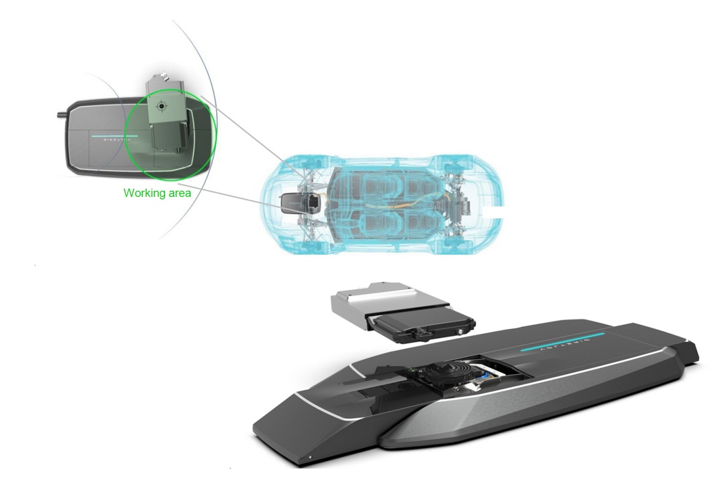
  • Connection and charging are carried out automatically; no precise parking necessary
    • 360° self centering conductive connector
      • Vehicle and Ground Unit are dirt, water and touch protected until contact established  
      • Ground Unit is plug & play installation

      • Vehicle Unit Dimension:  226/332 x 190 x 37 mm
      • Vehicle Unit Mass:  ~ 2 kg
      • Ground Unit Dimension:  795 * 440 * 68 … 77 mm
      • Ground Unit Mass:  ~ 25 kg
      • Working area:  400 mm diameter
      • Charging Power:  AC up to 22 kW,  DC up to 50 kW
      • Vehicle Unit Interface:  AC/DC power,  CAN to the vehicle,  WLAN to the Ground Unit
      • Ground Unit Interface:  Power (AC/DC) and CP/CC to the Wall Box infrastructure via Mode 2 connector or fix installation

      Ac2ated Sound

      • New design possibilities
      • Natural sound
      • Fewer channels/parts
      • Scalable system
      • Completely invisible
      • Less volume/weight
      • Reduced cost

      Overview ECU

      • Operating voltage 12V/24V (9…32V)
      • Operating temp.: -40°C to +85°C
      • Class D amplifier
      • 15W-35W / channel
      • CAN-FD supported
      • Protection class: min. IP6k9k
      • 2MB Flash (optional 8MB available for WAV files)
      • Weight: approx.: 250g
      • Dimensions: approx. 110 x 120mm

      Overview Basic Transducer

      • Operating temp.: -40°C to +105°C
      • Power rating: TL 10W; ST 20W
      • Frequency range: 200Hz -20kHz
      • Protection class.: IP6k9K
      • > 90dB (SPLmax)
      • Impedance: 4Ω
      • Weight: 68g (incl. housing)
      • Dimensions: 31.8 x 56.8 x 18.6mm (incl. housing)
      An illustration depicting an automated vehicle battery swapping system. It shows a car with its undercarriage exposed, highlighting the battery compartment. The system involves a robotic platform that slides out and swaps the car's battery with a new one.

      Sensors

      • Continental has developed a shunt-based current sensor for automotive applications for High Voltage Batteries in Hybrid or Battery Electric Vehicles. The sensor provides information about current, voltage and isolation independently to Battery Management System. The Current Sensor Module (CSM) communicates via CAN interface.  

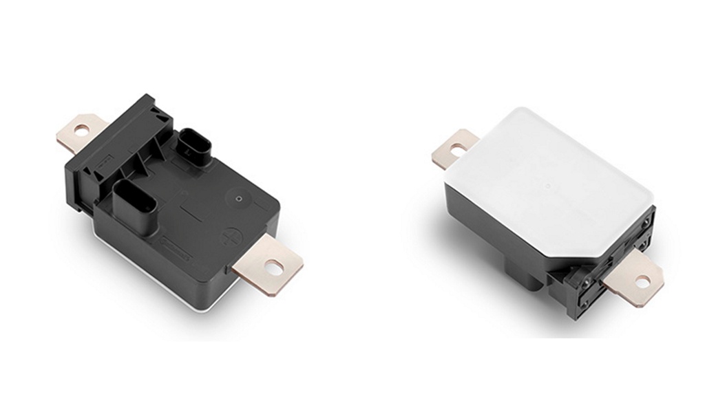
      • High Voltage range: 400/ 800V
        • Current measurement range: ±2000 A
          • Current measurement accuracy: ±1.0 %
            • Ambient temperature range: -40 °C … +85 °C
              • Voltage measurement accuracy: ± 1,5 % (optional)
                • Temperature Measurement range: -40 °C … +125 °C
                  • High precision safety relevant current measurement
                    • Supports up to ASIL D on system level by shunt / magnetic current sensors
                      • Compact design with integrated bus bar
                        • Galvanic separation of high voltage and low voltage area
                          • High speed measurements enable fast reaction on BMS level (e.g., battery cut-off)
                          Two views of a black and white automotive relay with metal mounting tabs. The relay on the left shows the bottom and side with electrical connectors and terminal prongs visible. The relay on the right is angled to show the top and one side.

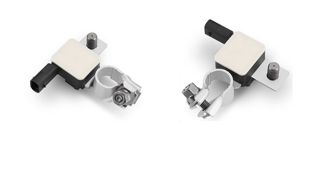
                          • The shunt-type IBS continuously analyzes the status of conventional 12-Volt lead acid batteries and provides information on such key parameters as the state-of-charge, state-of-function (power ability) and state-of-health (aging) of the battery. The sensor is thus essential to the reliable operation of automotive start-stop systems. The IBS is mounted directly onto the battery and fits exactly into the niche around the negative terminal.  

                          • Measurement range voltage: 5 V up to 18 V
                            • Measurement range current: -1500 A up to 1500 A
                              • Maximum Current for 2h (T<85°C) -200A up to 200A
                                • Accuracy SOC: 10 %
                                  • Accuracy SOH: 10 %
                                    • Accuracy SOF: 500 mV
                                      • Operating temperature: -40 °C up to 105 °C
                                        • LIN Communication
                                          • Supports CO2 reduction measures, such as intelligent alternator control or start/ stop function
                                            • Helps to avoid vehicle breakdowns caused by early warning of battery breakdown
                                              • Provides the battery’s State-of-Charge (SOC), State-of-Health (SOH), State-of-Function (SOF)
                                              Two identical rectangular electronic components with white tops and black bases, each attached to a metallic clamp. The clamps are fastened with screws and bolts. Both components are viewed from different angles, showing the details of the clamps and connectors.

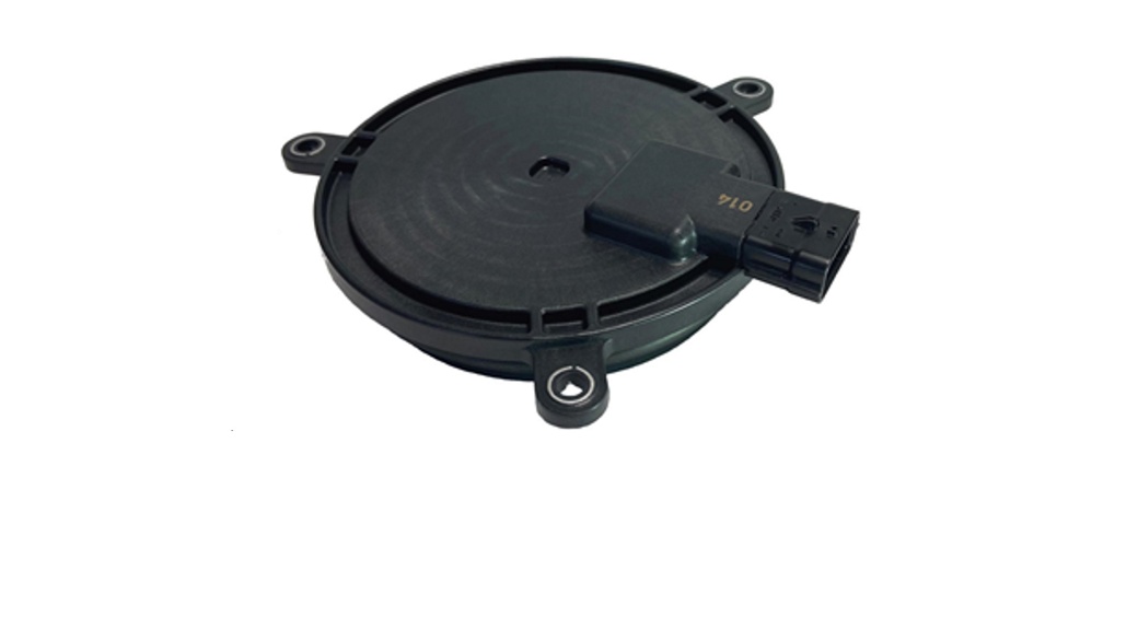
                                              • Measures the angular position of the rotor shaft in synchronous electric motors also at high speeds and accelerations with low delays.  
                                                • Integrated sensor protection for use in harsh outdoor environments.
                                                  • Generic sensor works with various pole pair e-motors.
                                                    • Sensor signal is needed for an efficient torque control in electric and hybrid vehicles.

                                                    • Protection Class: IP6K9K
                                                      • Operating Temperature: -40°C   to 150°C
                                                          • Operating Supply Voltage: 2.7V – 5.5V
                                                            • Current Consumption: max. 10mA
                                                              • Rotation Speed: 30.000 RPM
                                                                • Low current consumption
                                                                  • Sensor housing is smaller and lighter
                                                                    • Seals the shaft of the e-motor and provides cost-efficient assembly
                                                                      • No front-end-filtering function
                                                                      A round, black car speaker with a connector on one side and three mounting brackets around the edge. The surface has concentric circles and the connector has the marking "P10." The background is white.

                                                                      DC/DC-Converter

                                                                      • The DC/DC transfers energy between the different power nets in the vehicle
                                                                      • All variants are compliant to relevant EMC standards, voltage ripple and dynamic requirements
                                                                      • Development according to state-of-the-art automotive standards including functional safety and cyber security
                                                                      • Silicon, Silicon carbide and Gallium nitride technologies
                                                                      • Passive and liquid cooled version

                                                                      Continental 48V/12V DC/DC converter – Gen1
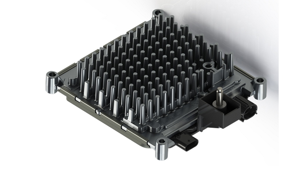
                                                                      A metallic heat sink component with numerous vertical fins designed for efficient cooling. It is mounted on a rectangular base with four circular support structures at each corner, and has an attached connector for power or data transfer.

                                                                      Continental 48V/12V DC/DC converter – Gen2

                                                                      A silver, rectangular electronic device with multiple ridges and two protruding connectors on the left side. The top surface features a series of vertical fins for heat dissipation. The device rests on a white background and appears to be housed in a metallic casing.

                                                                      A metallic heat sink component with numerous vertical fins designed for efficient cooling. It is mounted on a rectangular base with four circular support structures at each corner, and has an attached connector for power or data transfer.
                                                                      Image of an automotive electronic control unit (ECU) with connectors and a metallic casing, featuring a complex array of internal components and cooling fins.
                                                                      • Cost efficient design
                                                                      • Motor compartment compliant
                                                                      • High efficiency (>97%)
                                                                      • ISO26262 compliant, ASIL B
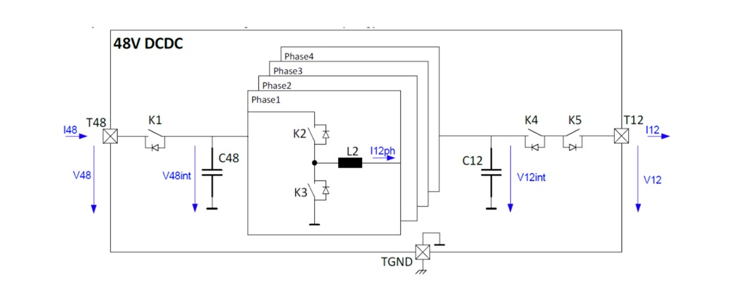
                                                                      A circuit diagram
                                                                      • Type:  Bi-directional operation (buck/boost mode)
                                                                      • Dimension (L x W x H):  213 x 187 x 70 mm
                                                                      • Mass:  1.4 kg
                                                                      • 12V operating voltage:  8V – 15.5V
                                                                      • 48V operating voltage:  24V – 56V
                                                                      • Power level:  1.78 kW (buck mode),  1.00 kW (boost mode)
                                                                      • Efficiency:  Typically > 97%
                                                                      • Cooling:  Naturally cooled
                                                                      • Control:  CAN
                                                                      • Environmental sealing:  IP6k6k / IP6k9k

                                                                      • Power Target:  
                                                                        Buck mode: 3.5kW continuous (4.2kW short time 5s)
                                                                        Boost mode: 1kW continuous
                                                                      • Peak Efficiency:  
                                                                        96.5% @3.5kW
                                                                      • Connectors:
                                                                        3x sealed stud bolt power connectors M8 (CL40, CL30, CL31).
                                                                        1x vehicle connector with 12 Pins (CL30e, CL31e, CL15, 2x CAN)
                                                                      • 48V Operating Range:
                                                                        Unlimited operating range: 36..52V
                                                                        Limited operating range: 31..36V and 52..54V
                                                                      • 24V Operating Range:
                                                                        Unlimited operating range: 10..32V
                                                                        Limited operating range: 8..12V and 32..36V
                                                                      • 12V Operating Range:
                                                                        Unlimited operating range: 6..16V
                                                                        Limited operating range: 16..18V
                                                                      • Software
                                                                        EB  AUTOSAR platform on 2-core µC  
                                                                        Security, UDS, J1939, Secured debug interface
                                                                      • Safety
                                                                        ASIL-B (functional safety concept is  defined by customer)
                                                                      • Cybersecurity
                                                                        Yes
                                                                      • Protection
                                                                        Voltage, Current and Temperature
                                                                      • Size
                                                                        Approx. length 280mm x width 175mm x  height 70mm
                                                                      • Volume
                                                                        ~3,5 lts
                                                                      • Weight Target
                                                                        ~2,2 kg
                                                                      • IP Rating
                                                                        IP67 + IP69K w/ plugged mating connectors
                                                                      • EMC Filter
                                                                        Yes


                                                                      A silver, rectangular electronic device with multiple ridges and two protruding connectors on the left side. The top surface features a series of vertical fins for heat dissipation. The device rests on a white background and appears to be housed in a metallic casing.

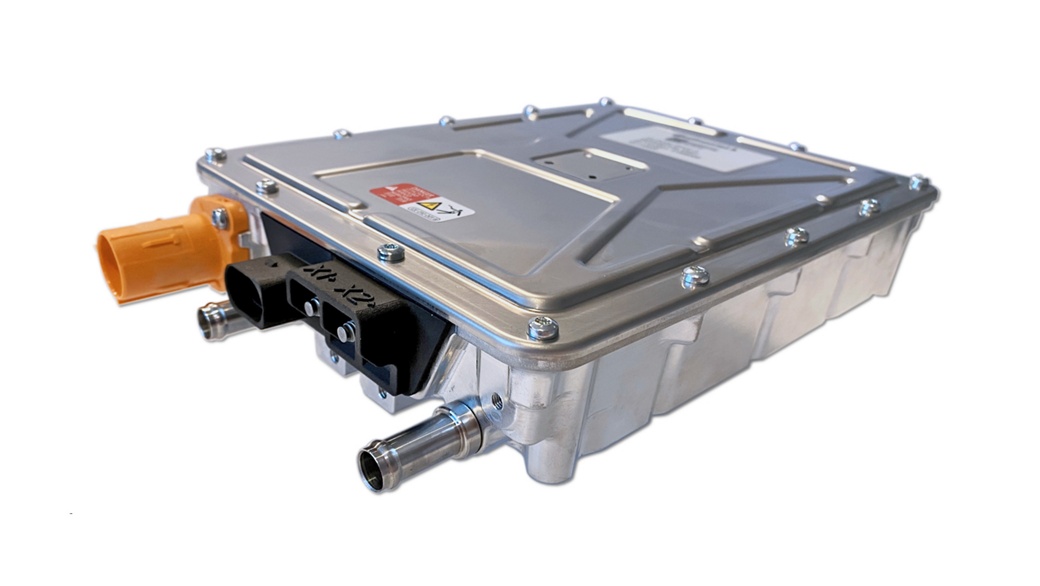
                                                                      A metallic electronic device with a rectangular shape, featuring a sealed cover held by several screws. It has connectors, including a large orange one on the left and two metallic cylindrical ones at the bottom. There are labels and markings on the top panel.
                                                                      • Compact Design
                                                                        • Easy to integrate
                                                                          • High efficiency (>97%)
                                                                          A circuit diagram
                                                                          • Type
                                                                            Buck DC/DC converter
                                                                          • Dimension (L x W x H)
                                                                            260 x 200 x 55 mm (w/o interfaces)
                                                                          • Mass
                                                                            4 kg
                                                                          • Input voltage
                                                                            270V – 450V (normal operation)
                                                                          • Output voltage
                                                                            10V – 48V (@ UIN>270V)
                                                                          • Peak power  
                                                                            2x5kW for 50s @ 4l/min at 65°C coolant temperature  
                                                                          • Efficiency
                                                                            Typically > 97%
                                                                          • Cooling
                                                                            Liquid cooled
                                                                          • Control
                                                                            CAN
                                                                          • Environmental sealing
                                                                            IP6k9k (A-Sample IP54)
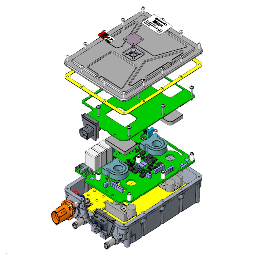
                                                                          An exploded view of an electronic device, showing multiple layers of circuit boards and components. The image highlights various interconnected parts, including a green circuit board, a yellow base, and an outer gray casing, along with connectors and screws.

                                                                          Features

                                                                          • Pre-charge functionality
                                                                          • Self-protection via derating, integrated diagnostics
                                                                          • Digital voltage and current control
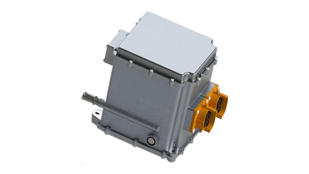
                                                                          Image of a gray, rectangular electronic device with a metal casing and several bolts around the edges. The device features large, orange connectors on the side and is isolated on a white background.
                                                                          • Silicon Carbide for high switching frequency
                                                                          • 83kW Peak power
                                                                          • 50kW continues power
                                                                          • High efficiency (>97%)
                                                                          • ISO26262 compliant, ASIL C
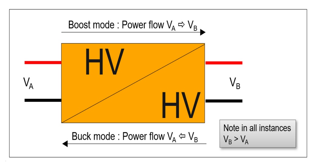
                                                                           A diagram showing a power conversion system with two modes. The left side is labeled V_A, and the right side is labeled V_B. In boost mode, power flows from V_A to V_B, and in buck mode, power flows from V_B to V_A. A note indicates V_B is greater than V_A in all instances.
                                                                          • Applications with two different power sources (e. g. fuel cell and high voltage batteries)

                                                                          Type
                                                                          Bi-directional operation (buck/boost mode)

                                                                          Dimension (L x W x H)
                                                                          310 x 240 x 210 mm

                                                                          Mass
                                                                          < 10kg

                                                                          Boost mode
                                                                          Input Voltage Range (VA): 180V to VB
                                                                          Output Voltage Range (VB):  VA to 820V

                                                                          Buck mode
                                                                          Input Voltage Range (VB):  VA to 820V
                                                                          Output Voltage Range (VA):  180V to VB

                                                                          Power level
                                                                          50 kW cont. / 83kW peak

                                                                          Efficiency
                                                                          Typically > 97%

                                                                          Cooling
                                                                          Liquid cooled

                                                                          Control
                                                                          CAN

                                                                          Ambient temperature
                                                                          -40 to +85°C

                                                                          Battery Management Systems (BMS)

                                                                          • The BMS monitors and controls the cells in a battery to provide the optimal performance and a safe operation.
                                                                          • Development of BMS solutions according to state-of-the-art automotive standards including functional safety and cyber security
                                                                          • Application SW with sophisticated BMS features (Diagnostics, SoC, SoH, Thermal Management,…), and AUTOSAR basic SW
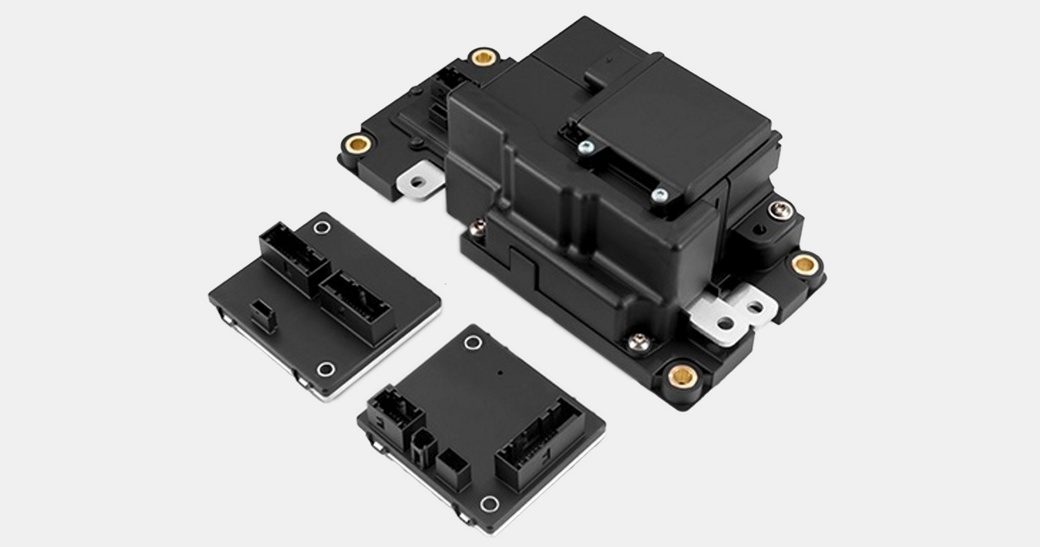
                                                                          Modular HV BMS
                                                                          Modular HV BMS
                                                                          48V BMS
                                                                          48V BMS

                                                                          Battery Main Controller.jpg

                                                                          BMC

                                                                          Battery Main Controller Aurix TC3 with Infineon SBC 3x CAN FD Main Battery IC Crash Interface H2 gas sensor

                                                                          Battery Disconnect Unit.jpg

                                                                          BDU

                                                                          Battery Disconnect Unit HV Voltage and Current measurement Basic Isolation monitoring

                                                                          Cell Supervising Electronic.jpg

                                                                          CSE

                                                                          Daisy Chain Battery ICs Cell Voltage and Temperature Measurement Load balancing (resistors external)

                                                                          Usual SW Work split

                                                                          CES provides:

                                                                          • AUTOSAR based BSW
                                                                          • Main Battery ASW

                                                                          Customer function content:

                                                                          • Battery cell algorithms and diagnostics
                                                                          • Can also be provided by CES

                                                                          ASW

                                                                          • Cell Overvoltage
                                                                          • Cell Undervoltage
                                                                          • Cell Overtemperature
                                                                          • Current Limit (I2 t)
                                                                          • Continuous Current Limit (>?)
                                                                          • Contactor Control
                                                                          • Communication with CSE
                                                                          • Isolation Measurement
                                                                          • Clamp 30c Monitoring
                                                                          • Interlock Monitoring
                                                                          • Pack Overvoltage
                                                                          • Pack Undervoltage
                                                                          • ECU Identification
                                                                          • Customer ASW Handler

                                                                          • State of Charge
                                                                          • State of Health
                                                                          • State of Energy
                                                                          • Operating Window
                                                                          • Operating Window Violation
                                                                          • In-Use-Histogram
                                                                          • Cell Balancing

                                                                          • Automotive grade cells
                                                                          • Automotive grade integrated BMS ( FSM: ASIL C, Cyber Security)
                                                                          • Integrated Solid-State Switch
                                                                          • Removable (hot swap)
                                                                          • Combination of multiple packs possible
                                                                          • CAN Communication
                                                                          Two black V4Drive battery modules by Continental stand upright on a surface. A blurred yellow scooter is in the background, adding a contrasting color to the scene. The handles on the front of the battery modules are visible, emphasizing their portability.
                                                                          • Nominal energy 1,6 kWh
                                                                          • Peak current: 230A (~11,5 kW)
                                                                          • Continuous current: 200A (~10 kW)
                                                                          • Mass: ~9,5 kg
                                                                          • LxWxH: 370mm x 90mm x 230mm
                                                                          c
                                                                          • A-Sample available
                                                                          ds

                                                                          Top Side
                                                                          Bottom Side

                                                                          • Support Multiple Li ion Chemistries   (NMC,LFP etc.)
                                                                            • Supports continuous current 75 Amp & Peak Current 150 Amp for limited time
                                                                              • In build pre-charge circuit available
                                                                                • Continuous monitoring of critical parameters i.e., Voltage, Current, Temperature, Isolation etc.
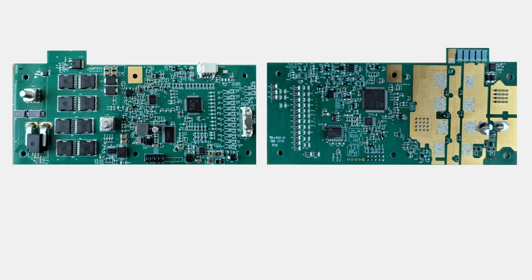
                                                                                  • ISO26262 complaint, ASIL C  

                                                                                  Type
                                                                                  Battery Management System  

                                                                                  Cell Configuration
                                                                                  3 to 16 Cells in Series  

                                                                                  Cell Voltage range
                                                                                  0.5 to 5 Volts

                                                                                  Balancing current per cell max
                                                                                  150 mA

                                                                                  Continuous Charge / Discharge current
                                                                                  75 Amp max  

                                                                                  Peak Charge / Discharge current
                                                                                  150 Amp max

                                                                                  Operating Temp.
                                                                                  -25 to +60°C

                                                                                  Storage Temp.
                                                                                  -40 to +85°C

                                                                                  Communication
                                                                                  CAN 2.0B

                                                                                  Wake Up Input
                                                                                  External Wk-Up available (5- 60 Volts)  

                                                                                  Top Side
                                                                                  Bottom Side

                                                                                  • Cell voltage supervision and balancing
                                                                                  • Pack voltage and current supervision
                                                                                  • SOC/SOH calculation and power prediction
                                                                                  • ISO 26262 capable (ASIL C)
                                                                                  • Cyber Security capable
                                                                                  • Integrated Solid-State Switch
                                                                                  • Electronic fuse
                                                                                  • Integrated pre-charge circuit

                                                                                  • up to 14s
                                                                                  • 3 temperature sensors
                                                                                  • Peak current: 230A
                                                                                  • LxW (mm): 255mm x 75mm
                                                                                  Block Diagram 48V Battery

                                                                                  • SOC calculation
                                                                                    Control of solid-state switches
                                                                                  • SOH calculation
                                                                                    Pre-charge control

                                                                                  • SOC calculation
                                                                                    Fuse blow detection
                                                                                  • SOH calculation
                                                                                    Fuse aging monitoring
                                                                                  • Power prediction
                                                                                    Pyro Fuse Firing circuit
                                                                                  • Data histogram

                                                                                    Pyro Fuse Diagnostic circuitry

                                                                                  • SOC calculation
                                                                                    Coolant flow rate acquisition
                                                                                  • SOH calculation
                                                                                    Coolant temperature determination
                                                                                  • Power prediction
                                                                                    Coolant control (fan, pump, valve)

                                                                                  • SOC calculation
                                                                                    Fault Management
                                                                                  • SOH calculation
                                                                                    UDS  Diagnostics
                                                                                  • Power prediction
                                                                                    Supply voltage monitoring
                                                                                  • Data histogram
                                                                                    Vehicle Communication
                                                                                  • Battery current sensing & monitoring
                                                                                    ECU Power Management
                                                                                  • Passive cell balancing
                                                                                    Wakeup Management

                                                                                  • SOC calculation
                                                                                    Thermal monitoring
                                                                                  • SOH calculation
                                                                                    Crash Signal sensing
                                                                                  • Power prediction
                                                                                    Cell voltage sensing &  monitoring
                                                                                  • Data histogram

                                                                                    Cell temperature sensing & monitoring

                                                                                  • Battery current sensing & monitoring
                                                                                    Pack Voltage measurements

                                                                                  • Battery cut off
                                                                                  • Homogenous sensing including vehicle variants
                                                                                  • Driver information & warning / contact information
                                                                                  • Severity of damage/repair recommendation

                                                                                  Temperature range
                                                                                  -40°C … 120°C

                                                                                  Protocol
                                                                                  PSI5

                                                                                  Functional Safety
                                                                                  up to ASIL B(D)

                                                                                  • similar design in series production > 10 years
                                                                                  • SOP ~2 years after nomination
                                                                                   Diagram showing a cutaway view of a large truck labeled "Continental." The left side illustrates a battery placement under the truck's chassis with an arrow from a car to the battery. The right side depicts the battery being removed downward with a mechanical arm.
                                                                                  side impact / curve driving

                                                                                  Tube with 2 pressure sensors

                                                                                  • tube compression
                                                                                  • sensor signal
                                                                                  • algo
                                                                                  • system reaction
                                                                                  Diagram illustrating a battery BID pSAT. A tube is shown entering the battery with an arrow labeled 'impact' indicating the direction of force towards the battery.
                                                                                  Vehicle Depelopment and Integration.jpg
                                                                                  E-Mobility for the Truck Market 

                                                                                  Vehicle Development and Integration

                                                                                  One Stop Shop from Concept to Serial Production

                                                                                  • Feasibility Studies
                                                                                  • Requirements
                                                                                  • Topologies, EE-Architecture
                                                                                  • Component Dimensioning
                                                                                  • Performance Simulation
                                                                                  • Development Plan
                                                                                  • Component Development  
                                                                                  • Vehicle Development
                                                                                  • Software and Control Development
                                                                                  • Technology Demonstrators
                                                                                  • Test Vehicles
                                                                                  • Fleet Vehicles
                                                                                  • System Integration
                                                                                  • Commissioning
                                                                                  • Logistics
                                                                                  • Performance
                                                                                    • Robustness and Reliability
                                                                                      • Safety and Misuse Crash Tests
                                                                                        • Prove of Legal Compatibility
                                                                                        • Homologation
                                                                                          • NEV Market Entry
                                                                                            • Industrialization
                                                                                              • Launch Support
                                                                                                • Production Support

                                                                                                Thermal Management Competencies

                                                                                                • Cooling and heating of the cabin by conversion of electrical energy
                                                                                                • Modelling of components and control algorithm including energy and thermal management
                                                                                                • SW development and Virtual Test of SW functions
                                                                                                • Optimization of control algorithms based on requirements
                                                                                                • Energy optimized algorithm‘s for electric vehicles

                                                                                                Aerodynamic Simulation

                                                                                                CFD Analysis

                                                                                                Four computer-generated images show fluid dynamics around a truck, using color-coded vectors to depict air flow. The images illustrate various perspectives and flow patterns. The truck is represented as a white silhouette against the colorful flow patterns.

                                                                                                Aerodynamics Appendage

                                                                                                 Illustration of a semi-truck with a detached roof segment highlighted beside it. The truck is shown in perspective view, and the roof segment, indicated by arrows, appears to be intended for the rear portion of the trailer.

                                                                                                Overview

                                                                                                • Evaluation of the aerodynamic efficiency of vehicle using detail steady and unsteady CFD analysis
                                                                                                • Minimization of  drag, emissions and energy consumption
                                                                                                • Recommend aerodynamics appendage
                                                                                                • Optimization of vehicle efficiency and consumption
                                                                                                • Optimization of downforce/drag ratio
                                                                                                • Improve aeroacoustics behavior

                                                                                                xEV Vehicle Build & Commissioning

                                                                                                Building up xEV prototype along vehicle development from first technology demonstrator to close-to-series test vehicle

                                                                                                Services

                                                                                                • Definition of interfaces to remaining vehicle
                                                                                                • Packaging components and systems into the vehicle
                                                                                                • Creation of E/E harnesses (low voltage, high voltage)
                                                                                                • Ensure communication of components and remain system
                                                                                                • Donor vehicle disassembly to BIW
                                                                                                  • BIW modifications
                                                                                                    • Mechanical and electrical integration
                                                                                                      • Integration of refrigerant and coolant circuit
                                                                                                        • Jig & Fixture design & build
                                                                                                        • Harness troubleshooting & rectification
                                                                                                          • Software alignment and updates (all ECUs)
                                                                                                            • HV safety commissioning (2 levels)
                                                                                                              • ADAS systems & chassis alignment
                                                                                                                • Full vehicle static & dynamic testing and mileage accumulation

                                                                                                                Do you want to know more?

                                                                                                                *If the contact form does not load, please check the advanced cookie settings and activate the functional cookies for the purpose of contact management.